Learning topic
Machine-Element Joints
Classification, load transfer, selection and basic design of detachable and permanent machine-element joints.
Machine-element joints combine separate parts into assemblies and transfer forces, torques, and motion. A correct model follows the complete load path through bolts, welds, rivets, keys, splines, adhesive layers, or interference surfaces.
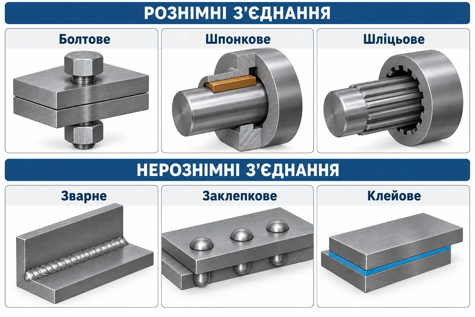
Classification
Detachable joints include threaded, keyed, splined, and clamped connections. Permanent joints include welded, riveted, soldered, and adhesive connections. Interference fits occupy an intermediate position because dismantling is possible but may damage the fitted surfaces.
Load can be transferred by form closure, frictional closure, or material closure. This distinction determines the appropriate equations and failure modes.
Тип з’єднання обирають за сукупністю вимог: можливістю розбирання, характером навантаження, матеріалами деталей, технологією виготовлення та умовами експлуатації. Таблиця дає орієнтовне порівняння найпоширеніших варіантів.
| Критерій | Різьбове | Шпонкове / шліцьове | Клемове | Зварне | Заклепкове | Паяне / клейове |
|---|---|---|---|---|---|---|
| Розбирання без руйнування | ● Добре | ● Добре | ● Добре | — Недоцільно | — Недоцільно | — Недоцільно |
| Передавання крутного моменту | ◐ Можливо | ● Добре | ● Добре | ● Добре | ◐ Можливо | ◐ Можливо |
| З’єднання тонких листів | ◐ Можливо | — Недоцільно | — Недоцільно | ◐ Можливо | ● Добре | ● Добре |
| Різнорідні матеріали | ● Добре | ◐ Можливо | ● Добре | — Зазвичай недоцільно | ◐ Можливо | ● Добре |
| Герметичність | ◐ З ущільненням | — Недоцільно | — Недоцільно | ● Добре | ◐ Можливо | ● Добре |
| Регулювання положення деталей | ◐ Можливо | ◐ Обмежено | ● Добре | — Недоцільно | — Недоцільно | — Недоцільно |
Позначення: ● — добре відповідає критерію; ◐ — застосування можливе за певних умов; — — зазвичай недоцільно.
Оцінки не є абсолютними. Остаточний вибір залежить від величини та характеру навантаження, матеріалів, точності складання, корозійного середовища, серійності виробництва й вартості.
Main groups
- Threaded joints: standardized and serviceable; preload can transfer transverse load by friction and reduce bolt load fluctuation.
- Keys and splines: transmit torque between a shaft and hub; splines improve centering and distribute load among several teeth.
- Clamped joints: use normal pressure and friction without cutting a keyway.
- Welded joints: offer low mass and high rigidity but require control of stress concentration, distortion, residual stress, and quality.
- Riveted joints: rivets are checked mainly for shear and holes for bearing.
- Soldered and adhesive joints: suit thin or dissimilar parts but depend strongly on surface preparation, overlap geometry, temperature, and environment.
General design logic
First determine design actions:
$$F_d=K_dF,\qquad T_d=K_dT.$$
Then establish the load distribution and check all credible limit states:
$$\sigma\le[\sigma],\qquad \tau\le[\tau],\qquad p\le[p],\qquad n=\frac{R}{S}\ge n_{min}.$$
Selection also considers assembly, inspection, fatigue, corrosion, sealing, accuracy, stiffness, mass, and cost.
Load paths and joint stiffness
A joint must be analyzed together with the connected parts. Local flexibility changes force distribution: the stiffest fastener or shortest load path may attract more load than an equal-share model predicts. Contact opening, slip, prying action, eccentricity, and secondary bending are therefore checked explicitly.
Static and cyclic actions
For a repeated action, use mean and alternating components,
$$S_m=\frac{S_{max}+S_{min}}{2},\qquad S_a=\frac{S_{max}-S_{min}}{2}.$$
Bolted and welded details are especially sensitive to stress concentration. Preload may reduce bolt stress amplitude, whereas weld toes, holes, keyways, and thread roots often remain fatigue-critical.
Stiffness, sealing, and positioning
Strength alone is insufficient when a joint locates bearings, gears, guides, or seals. Interface pressure and fastener layout must preserve alignment and prevent local opening. Dowel pins, fitted bolts, shoulders, pilots, or splines should locate parts; ordinary bolts should not be assumed to provide precision positioning through clearance holes.
Manufacturing and inspection
Design should provide tool access, repeatable tightening, suitable weld positions, controlled adhesive gaps, measurable interference, and inspectable surfaces. Specify which dimensions control function and which defects are unacceptable. Permanent joints require an inspection method compatible with the expected defect orientation.
Typical causes of failure
- incorrect load path or neglected eccentricity;
- loss of bolt preload and joint slip;
- fatigue at a notch, hole, thread, or weld toe;
- fretting at nominally stationary interfaces;
- creep, relaxation, corrosion, or thermal mismatch;
- assembly damage or uncontrolled friction.
Selection sequence
- Decide whether dismantling or adjustment is required.
- Choose form, friction, or material closure.
- Lay out the joint so the load passes with minimum eccentricity.
- Calculate the individual elements and connected parts.
- Verify stiffness, fatigue, environment, assembly, and inspection.