Learning topic
Shafts and Axles
Design of shafts and axles for bending, torsion, fatigue, stiffness, stability and dynamic performance.
Shafts support rotating elements and usually transmit torque. Axles mainly support rotating parts and do not normally transmit torque. Both are designed as load-carrying beams with stepped geometry, seats, shoulders, grooves, and stress raisers.
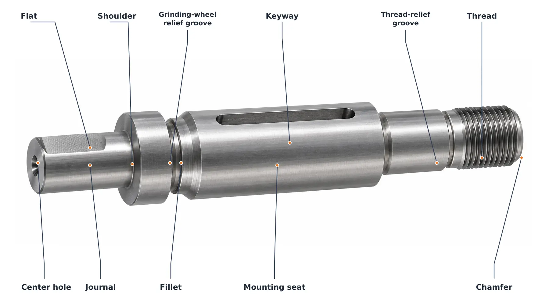
Loads and internal actions
Gear, belt, chain, coupling, weight, and inertial forces are resolved in two perpendicular planes. Bearing reactions are found from equilibrium; bending moments are combined as
$$M_b=\sqrt{M_y^2+M_z^2}.$$
Torque follows from transmitted power:
$$T=\frac{9550P}{n}.$$
Strength
For a solid circular section,
$$\sigma_b=\frac{32M_b}{\pi d^3},\qquad \tau_t=\frac{16T}{\pi d^3}.$$
A static von Mises check is
$$\sigma_{eq}=\sqrt{\sigma_b^2+3\tau_t^2}\le[\sigma].$$
Critical sections are usually shoulders, keyways, splines, grooves, threads, and fitted seats. Stress concentration and size, surface, and reliability factors must be included in fatigue design.
Stiffness and dynamics
Deflection and slope affect gear alignment, seals, and bearing load distribution. The twist is approximately
$$\varphi=\frac{TL}{GJ}.$$
Long or high-speed shafts are also checked for lateral critical speed, torsional vibration, and—when axially compressed—buckling. Design is therefore iterative: establish forces, size the shaft, define the construction, verify fatigue and stiffness, then update bearing reactions and fits.
Constructive design
Shaft diameter changes create seats for bearings, gears, seals, and couplings. Shoulders provide axial location; fillets reduce stress concentration; grooves accept retaining rings or relief tools. The designer must reconcile fatigue-friendly radii with bearing chamfers, grinding reliefs, assembly paths, and available standard diameters.
Free-body diagrams
Loads are applied at their real planes of action. A gear may supply tangential, radial, and axial components; a pulley supplies the vector sum of belt tensions; a coupling may add radial force or bending moment when misaligned. Reactions are solved in both transverse planes, then axial equilibrium is considered separately.
Fatigue verification
Rotating bending under a stationary transverse load is fully reversed at a material point. Torque may be steady or fluctuating. A common design representation combines corrected alternating and mean stresses using an appropriate fatigue criterion. Stress concentration factors are converted to fatigue notch factors according to material notch sensitivity.
Deflection and alignment
The shaft is modeled as a stepped beam with concentrated and distributed forces and elastic bearing supports when necessary. Limits are imposed on deflection at gears and seals, slope at bearings, and relative displacement of meshing elements. Increasing diameter is usually more effective than changing material because bending stiffness scales with \(d^4\).
Dynamic behavior
A rotor must operate sufficiently far from bending and torsional natural frequencies or pass through resonance safely. Added discs, couplings, and gears change mass distribution; bearings and supports change stiffness and damping. High-speed shafts require balance grades consistent with operating speed and sensitivity.
Design sequence
- Prepare the layout and calculate external forces.
- Find reactions, bending moments, torque, and axial force.
- Estimate diameters from static strength.
- Develop shoulders, seats, fillets, keys or splines, and axial retainers.
- Verify fatigue at every critical section.
- Check deflection, slope, twist, critical speed, fits, and manufacturability.